Diamond Drilling, Core Logging and Core Sampling Processes
Below is a brief summary of various aspects of diamond drill testing, core logging and core sampling of rocks and ores recovered from deep below the bedrock surface. The description is intended to explain these processes to interested persons that have little knowledge of mineral exploration and mining industry. Investors may find the explanations useful to better understand nuances of the mineral industry. Some of the concepts may be useful for geologists that are new to the mineral exploration industry. It is designed to be the resource I wish was available in the early 1970’s when I started logging core.
The mineral industry uses a diamond drill to recover a continuous string of core to examine the geology of the ground they are testing. Diamond drillers use three meter long steel rods with a diamond impregnated bit at the bottom to cut a core of rock from the bottom of the hole. The bottom rod is a specialized three meter long, hollow core tube which passes over the core as the rock is cut by drill bit. The core is retrieved and placed in a core box. The drill rods screw together forming a drill string extending from the drill to the bottom of the hole. The core is best envisaged a continuous core string of interlocking pieces that represent the rock cut by the drilling process. The drillers identify the length of the hole and the location of the core in the core string by tracking the number of rods in the hole.
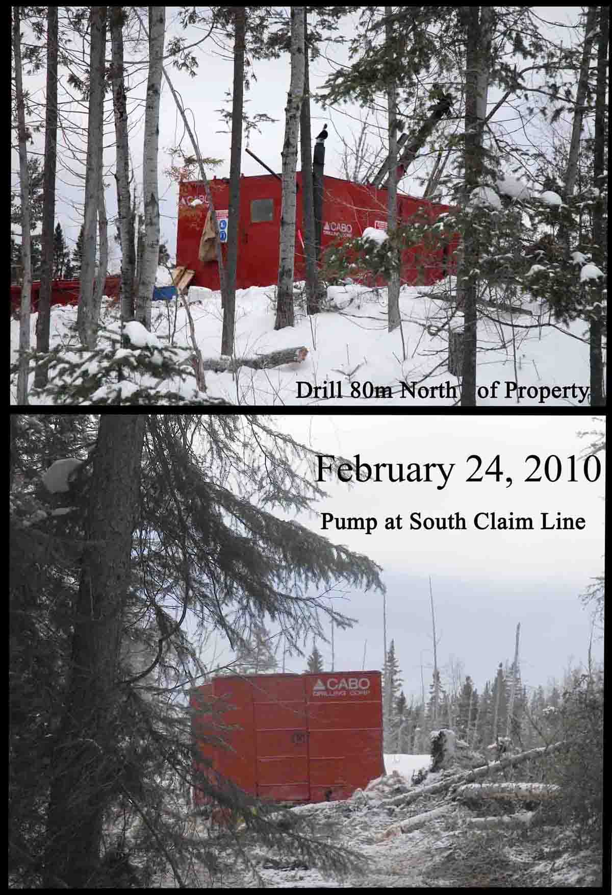
Picture Above: The top picture is a diamond drill testing for gold near my Eby Township property that is in Eby Tp. The bottom picture is the pump shack that holds the pump that pumps drill water to the drill. These Eby-Otto Tp. claims are available for option
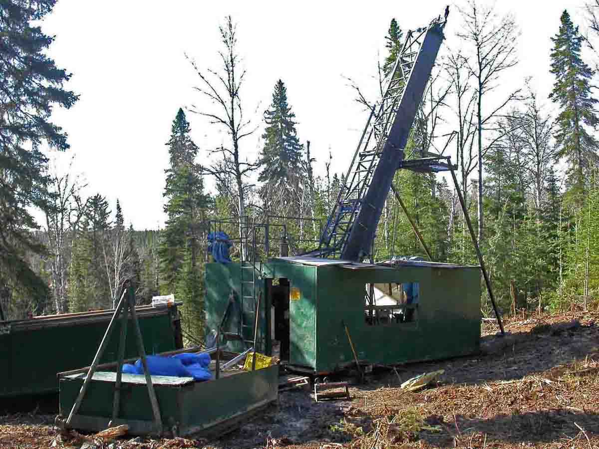
Picture Above: Diamond drill testing a local cobalt vein. The drill is in the enclosure with the high drill mast. The drill mast supports the rods when these rods are out of the hole to change the bit. The low sled holds the drill rods used to drill the holes.
The drillers and the geologist reference the core to the top of the hole which is usually a large diameter pipe called” casing”. The casing is a large diameter steel pipe that protects the hole in the overburden (soil) between the drill and the bedrock surface. A diamond impregnated casing shoe (diamond bit) at the bottom of the casing is used to drill a short distance onto bedrock. Drilling the casing into bedrock prevents soil and rocks from caving into the hole. The inside of the casing is significantly larger than the drill rods. The drill rods drill the hole from inside the casing.
When a hole is completed the casing is generally left in the ground and capped. If the casing is left in place, contractors can reenter the hole to continue drilling, or to conduct in-hole surveys that determine the trajectory of the hole, or to photograph the inside of the hole or to conduct geophysical surveys including: Magnetic, Electromagnetic (EM), Induced polarization (IP) surveys.
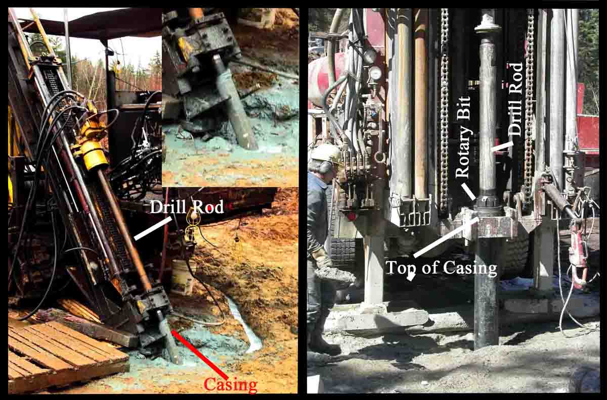
Left Picture Above: The diamond drill casing extends from about 12 inches (30cm) above ground to a foot or two into the bedrock. The drill rods extend from the drill (head) to the rock face here the drill bit cores the bedrock. See the details in inset.
Right Picture Above: This is a rotary drill testing the A4 Kimberlite Pipe NE of Kirkland Lake Ontario. The casing extends from approximately 3 feet above the ground into the bedrock below the overburden.
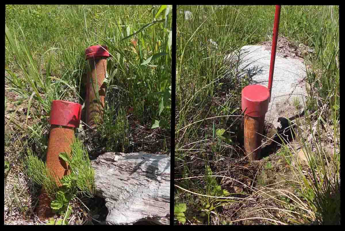
Picture Above: Diamond drill casings. The drill casing caps protect the casing from damage and prevent material from entering the hole.
Drillers Three Meter Reference Marks on the Core
All hole measurements, including geological logging is referenced to the top of the casing (0.00meters). The driller’s helper inserts Depth Markers into the core string at 3 meter intervals. The helper tracks the number of rods in the hole and inserts a new depth marker after each rod length. Three times the rod count is the depth of the hole. These depth markers are the only means the geologist has to determine the depth of the geological features to be logged.
The core does not break at exactly three meter intervals. The distance between the depth markers commonly ranges from 2.85-3.15 meters. This apparent discrepancy is the best case scenario, and is the industry norm for high quality drilling. In high quality drilling these small discrepancies average zero meters. The geologist can determine (deem) a depth references point using the average position of multiple depth markers. Correcting the depth markers takes some time, but this time is regained by faster logging and accurate and precise sample lengths used to calculate grades.
Core Orientation in the Core Box
The driller’s helper places the core in core boxes for permanent storage and transport. The core boxes commonly used in northeastern Ontario are wooden containers with three or four grooves to hold the core. Each groove holds approximately 1.4 meter (4.6 ft) of core. In the old days; when I started logging, small diameter core in five row boxes was the norm.
It is always important for everyone in the drilling and logging process to be constantly aware which end of every piece of the core is the upper end. The driller’s helper places the uppermost piece of core in the back (upper) left corner of the box and fills the first row with consecutive matching pieces of core. When the first row is filled the second row is also filled from left to right. This is repeated for each row until the box is full. The geologist then reads the core like a book from upper left to the lower right. Each box is a page in that book.
It looks like the drill helper’s job is straight forward and easy. This is not the case. It is very easy to reverse the core tube and place the entire core run backwards into the core box. Also; when emptying the core tube, a piece of core flips end for end ends up backwards in the box. The geologist and all other core handlers must also be careful to return all core to the box in the correct orientation.
Precision of Logging Measurements
As a geologist I measure all points to 1 cm precision. This precision appears to be artificial considering the larger errors in identifying the location of the point in space and along the hole depth. If the depth marker identifies the ends of the hole as 302 meter, my log may record the hole depth as 301.87 meters at that location. Nether number is more accurate than the other. The logging precision is required to accounts for the random 15-30 cm discrepancies in the depth markers.
Assuming the errors in the depth marker location ore random, it is safe to assume the error averages 0.00 meters. The geologist can deem a depth references using the average position of multiple depth markers. Correcting the depth markers takes some time, but this time is regained by faster logging and accurate and precise sample lengths used to calculate grades. No depth markers should be moved. Instead, new pencil crayon depth markers are penciled onto the core at 1.00 meter intervals.
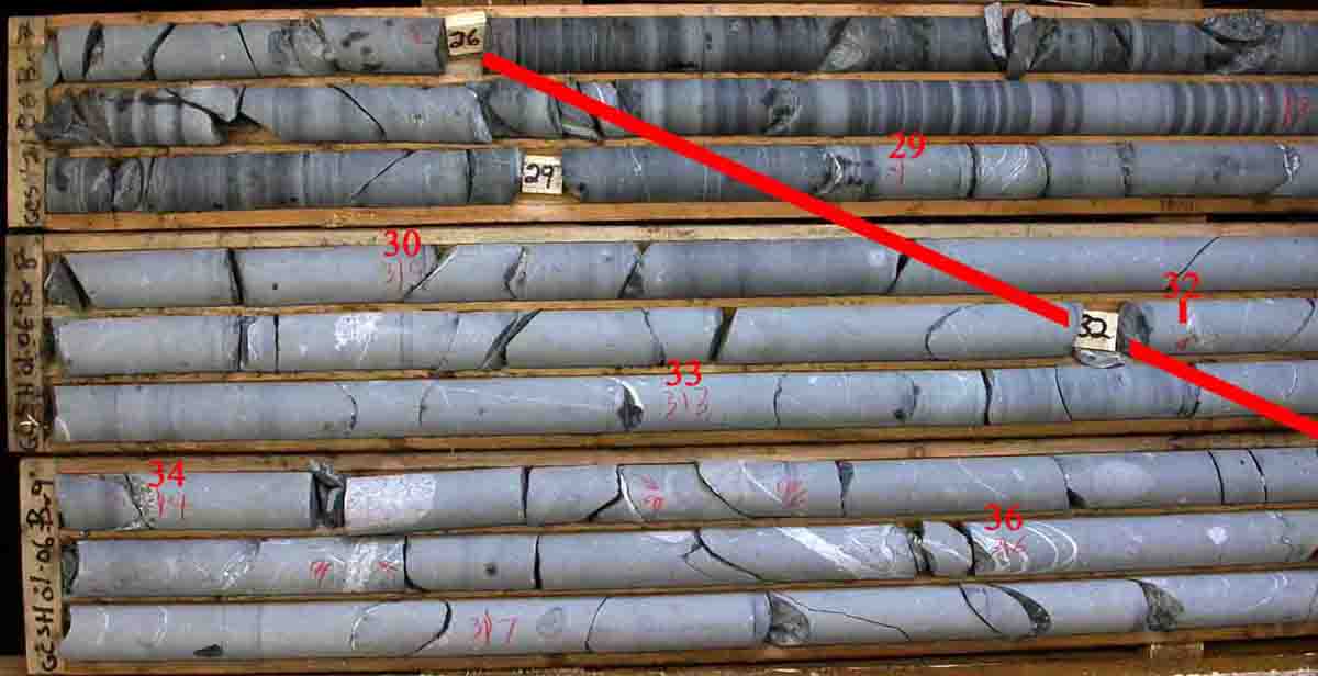
Photo Above: In the core above the 26 meter depth marker was deemed correct and all the color penciled depth markers were measured from that marker. The 29 meter depth marker is conspicuously offset from true location relative to the other markers
In normal core the depth markers appear to shift approximately 20 cm to the right from the previous marker. This displacement is caused by the expansion of the core across fractures. With practice the geologist becomes proficient at compensating for this expansion.
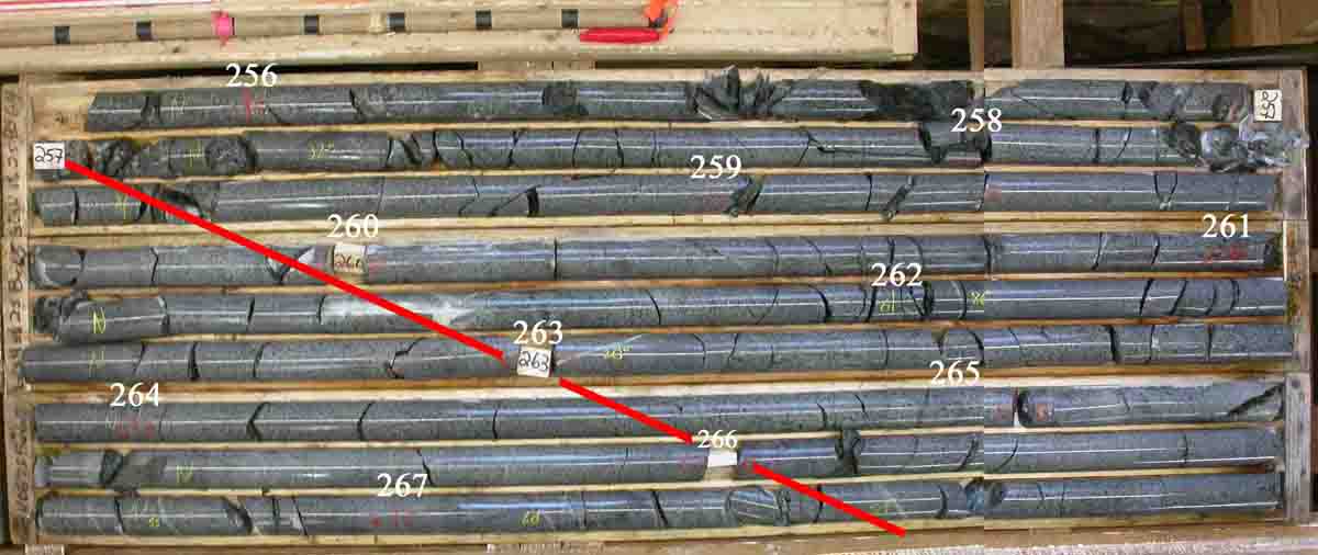
Photo Above: This core has the reference marks established at 1.00 meter intervals The original depth markers in this core are near perfect core with all the original drill markers very near 3.00 meters apart.
Precise measurements come into play when defining lost core and assigning core lengths to assay samples. No gaps or overlaps of measurements compute can be accommodated in weighted average grade calculations.
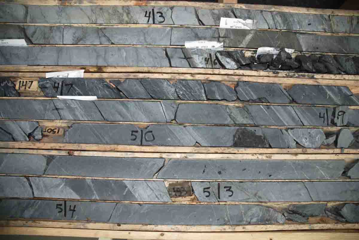
Photo Above: The discrepancies between the original depth markers in the above photo demonstrate the need for precise and accurate corrected depth measurements to assign reliable sample lengths required for accurate weighted average grade calculations.
Nitty Gritty Logging Details
The logging processes described below are the all-inclusive procedures that I use for detailed logging. If only a short section of the hole requires detailed logging, the standards for the unimportant portions of the hole can be relaxed.
These procedures described below are viable for competent rock with excellent core recovery. Other viable procedures exist. Some of these measurement procedures do not work in friable, badly broken or sheared/faulted core. In these problematic rocks; the depth markers may have to be accepted as accurate unless there in strong reason to believe the markers are not accurate.
Photo Above: In badly broken core such as this the geologist may have to make arbitrary decisions concerning accuracy of depth markers. In some cases the markers are deemed to be correct.
Commonly only a short section of the hole is important and a reference marker within or close to the important core is deemed precise for all measurements within the key logging area. This shortcut still requires that all the drill markers above that location be accounted for and any errors compensated for. Common problems encountered include:
- Repeated depth markers such as two markers both labeled 257 meters that separated by 3 meter of core.
- Skipped intervals such as depth markers 248 and 254 meters separated by 3 meters of core.
- Depth markers labeled at other than 3.00 meters such as a string of labels 248, 251, 253 and 256. In this core string, 3 meters of core is reported as 2.00 meters between the 251 and 253 depth markers.
A viable correction is to stroking out the incorrect driller’s location, invert the depth marker and correcting the location on the back of the marker (using a large lead, HB or B). The depth marker should not be corrected by moving the marker.
It is sometimes necessary to log the important sections of core first and fill in the low priority core later when time permits. It is extremely awkward to log the key deep portion of a hole and later find depth marker errors towards the collar of the hole. Often when a driller tries to correct an error another error is created and logging can quickly become tedious. The solution is to at least certify the validity of the depth markers between the from the top of the hole to the logging area. Errors of a meter or less are not important and can be reported in the log without correction.
The driller’s depth markers in the first six meters of recovered core commonly have significant errors and should not be used as reliable reference for the rest of the hole. It is best to measure the core locations up and down the hole from a reliable reference marker (commonly the first reliable depth marker). The logs should also include the bedrock surface reported by the driller and the bedrock depth the geologist calculates.
If a long section of core is laid out for logging, each core marker tends to be located approximately 20 cm to the right of the last depth marker. The logger can visually spot the depth markers that are out of place and spot the markers that are reliable.
- A depth marker that appears to be correct relative to the other markers is arbitrarily deemed correct.
- The core is measured up and down the hole from the depth marker that was deemed correct. Every meter interval of core is marked off with a colored pencil crayon line across the core and the depth label is inscribed in bold numbers.
- If most of the other depth markers fall a consistent offset distance from penciled depth marks, one of these marks can be deemed correct and the core remarked, possibly with a different color. The more appropriate set of penciled depth marks is deemed correct and darkened and the depth marks conspicuously numbered as meters from the collar.
Quickly and accurately establishing accurate and precise 1.00 meter interval depth meter depth marks takes practice. The effort is compensated for by saved logging time and greater confidence in logging critical measurements. One hundred 75 meters well laid out core can be marked up in 15-25minutes.
If the drillers placed the core haphazardly into be boxes, the core markup it is time consuming and frustrating work.
When problems are encountered; first check to determine if an entire 3 meter core run has been inserted backwards into the box. One reverse run is an easy problem to solve. The problematic 3 meter run can be corrected placing that core in the correct orientation in a replacement box. The entire run can then be returned, correctly oriented to the original box.
Sometimes core from an entire shifts can be reversed. If consecutive runs are reversed it is easiest to simply move all the core to new permanent boxes while correcting the orientation. If long sequences of reversed core are logged, the illogical configuration of rock type scan be the red flag setting off the alarm bells saying re-log the core.
Sometimes jumbled core is randomly out of order core and/or reversed core. Fortunately this problem is commonly restricted to an individual 3 meter which is independent of the runs above and below the problem. Consecutive runs can be a problem but the problems with one run is independent of the problems other runs. Core runs need not end at the depth markers and finding the end of any run can be difficult. If he end of one run is found the core can be pieced upwards and downwards from the point.
Sometimes if the core is from a low priority section of the hole you simply give up.
Establishing 1.00 Meter Depth Marks
It is wise to not move the depth markers. Color pencil crayons are excellent to mark the geologists meter reference marks at 1.00 meter intervals. , orange, bright blue and white colored pencils work are conspicuous on most core.
Picture Above: This core shows both orange and white logging inscriptions.
Problems such as severely broken ground, over-ground core and mine workings can prevent continuous determination of 1.00 meter depth markers along the entire core string. In this situation: A precise depth reference point can be established and deemed correct above the problematic interval and another depth reference point established below the problematic interval.
The 1.00 meter interval depth determinations can be extended down into the problem area and up into the problem area. Within the problem area the depth markers need to be established as a best fit and error accepted.
Much of the error may be reported as lost core. It may be possible to establish the probable location of the lost core. Where the lost core location cannot be established it is practice to arbitrarily log an interval as lost core with the log note “Arbitrarily logged as lost as lost core to accommodate logging and sampling.
Sometime there appears to be extra core. Which cannot happen in perfect measurements. This is caused by the apparent expansion of the core string due to many, possibly hundreds of breaks in the core. In this situation, a best fit correction must be made. The apparent error is easily distributed evenly between each row of core in the broken area.
Core Table Size
Large core logging table facilitates quick, consistent and reliable core logging and certification of true core location markers and logged intervals. It is important to certify that all 3 meter interval depth markers are within acceptable 15 cm scatter of the ideal 3.00 meter interval and no numbering errors occur in the hole. By doing this the geologist has assurance the depth marker locations are probably correct within industry norms. By reading and verifying each depth marker is at the correct 3 meter interval is counted correctly.
A simple two minute walk down the table observing and reading each depth marker verifies the quality of the core depth measurement in 75 meters of core.

Photo Above: Excellent core logging facility to establish 1.00 meter depth markers
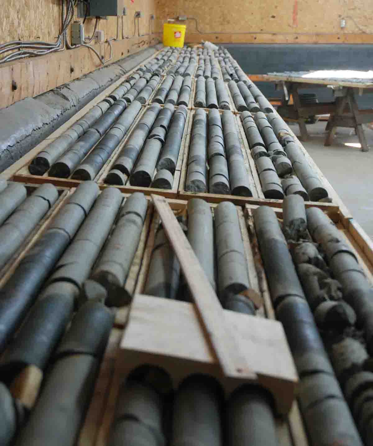
Picture Above: Another Excellent core logging facility to establish 1.00 meter depth markers
It may not be practical to establish precise 1.00 meter depth markers in f the mundane core outside the area of interest. However the 3 meter interval depth markers for the entire hole should be accounted for as reasonable in the correct sequence with no mathematical errors, omissions or repetitions. It does not matter if measurements in this mundane core have 10 to 20 cm non-cumulative errors.
In severely broken ground accurate 1 meter depth intervals are difficult. However an attempt to determine accurate depth marks is required to determine lost core that was over-ground during drilling. If there is a possibility that ore occurs in bad ground, it is necessary to make the best possible core interval determinations for accurate core interval measurement and accurate grade calculations.
Photo Above: It is difficult to determine accurate 1 meter interval depth marks in this core. Assuming the depth markers 121 and 124 meters are correct, it appears that 0.20-3.0 meters of core was lost (ground) core in this interval. It is more likely errors in placing the depth marker are the reason for this apparent ground core. The probable depth determinations of all core from above to below the bad ground has to be accounted for to determine the amount of core ground.
Core Sampling Intervals
A common practice in core sampling or any other sampling is to not allow the sample interval to cross a significant contact, alteration, mineral suite or ore control. This is a sound sampling procedure to maximize the available, useful information. This can be critical to understanding the geology and geological ore controls.
Core Sample Lengths
Some geologists attempt to sample core in exactly 1.00 meter long sample intervals. This is one of the excellent sample protocols. It is impossible to consistently break the core with one cm precision. The core must be cut precisely along the 1.00 meter end of sample mark. This cut can be done before the core is split or the sawn half of core destined for assay can be cut along this line.
This procedure is requires the core is cut across the core at the exact one meter sample interval. Also breaking the core is unnecessarily shatters the core making it much less useful for future work. Also the core splitter is unlikely to report the inevitable problems encountered.
Personally; I prefer to assign sample intervals to natural breaks in the core. If the core is not broken near the ideal end of sample I break the core as near that ideal location as possible and assign the sample length to this new break. In a few situations a precise predetermined end of sample is required and the core must be cut along the end of sample line. This precise cut is required to assure the core reports to the correct assay sample.
When sampling long sections of core with no apparent reason to split the sample at specific locations; it is appropriate to run a sample from one end of the core box to the other end of the box. These situations include low priority sampling, sampling to determine open pit potential or sampling rock that is likely waste. Samples ending at the ends of core rows average 1.4 meters of core.
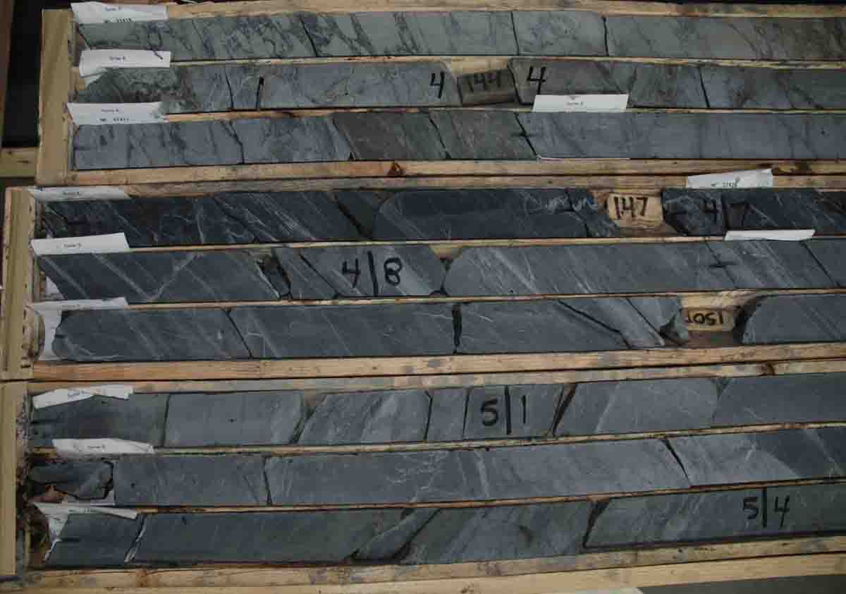
Photo Above: The boxes of core include both box end to box end samples and core rows divided into multiple samples. Every depth mark, sample tag and wooden depth marker can be destroyed or lost and the entire sample sequence can be re-established to 0.01 meter accuracy and precision.
When sampling priority core it is good to establish two of more samples in a core row with the end of the core rows marking ends of samples. In this scenario the individual rows commonly have two or three complete samples. When using this protocol there will be exceptions based on sound geological reasons.
Marking Ends of Core Samples
Geologist commonly mark the ends of core samples by placing a paper sample tag at the leading edge of the sample. This process has severe problems if the core shifts in the box or if the core is becomes jumbled or commonly handled. It is exasperating and sometimes impossible to verify the sampling of core because many sample tags and many core markers are shifted and/or are missing. This problem is common in drill core.
One easy way to prevent this problem is to end samples at the end of core box rows and to physically mark both ends of every sample with a permanent, easily identified mark. Felt pens are not permanent because they fade.
If these are done consistently; the sample interval can be reconstructed accurately and precisely to 0.01 meter even if every drill marker and every penciled logging marks are lost or destroyed. This reconstruction of the hole can be performed using the sample log and the aluminum box end tags. It is aggravating to re-log an old hole where little information can be certified or verified with confidence because the core, sample tags and the depth markers have moved in the box ore or are lost.
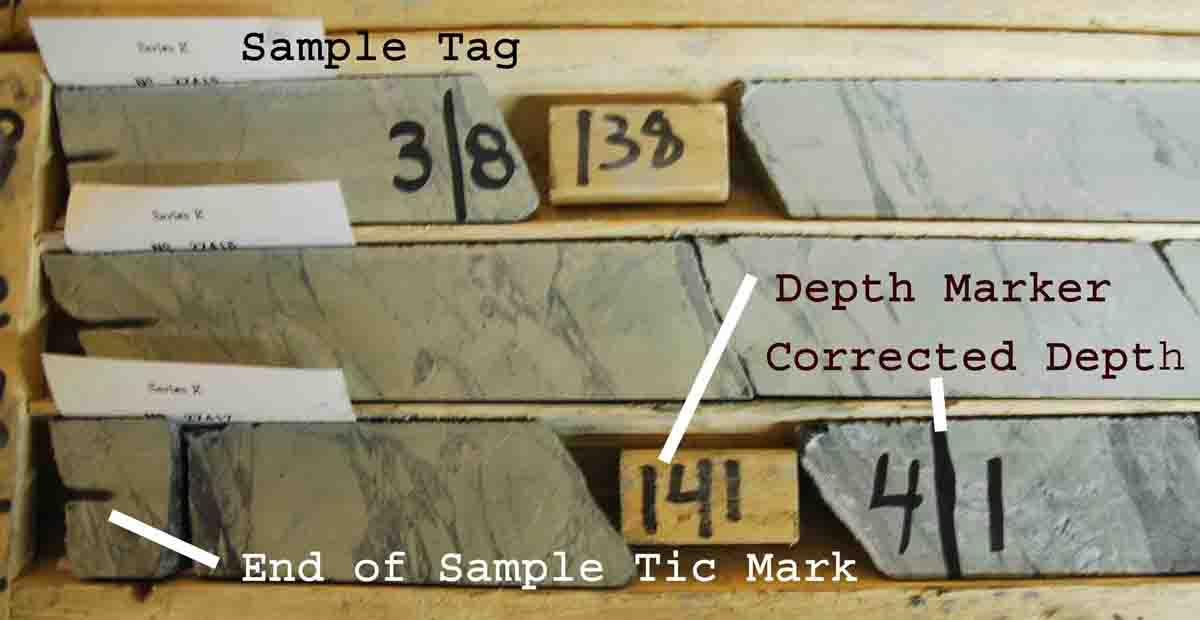
Photo Above: Both ends of every sample are permanently marked. If all the depth tags and other geologist’s marks were to be lost; the entire interval of split core can be verified to 0.01 meter precision and accuracy using only aluminum core box tags on the box end and the sample interval log. The bottom side of the core is marked by orange colored pencil and some depth marks were transferred to the front when the core sample was bagged.
Core Sampling Intervals and the SG Effect
If a very high grade silver intersection is assayed over a vein width it gives maximum information about mineralogy. However the vein may have an SG of 5.6 within a wall rock with an SG of 2.8. In this situation; measuring the SG of the vein and the SG of the wall rock can double the reported grade of the intersection. I have not encountered reported grades of silver intersections that take this into account. To not compensate for SG would reduce the apparent silver content of this intersection to 50% of the actual silver value.
If a similar 5 cm highgrade silver vein is included in 95cm of wall rock the SG effect of the ore is almost compensated for by dilution from the wall rock. To not compensate for SG would reduce the apparent silver content of this intersection to approximately 95% of the actual silver value.
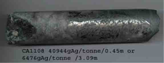
Photo Above: The Vein SG is 3.42g/cm3 over 0.45m. The wall rock has an SG ranges from 2.91 to 2.96 g/cm3. The core grade was not SG corrected for Sedar reporting. This means the Silver content reported is 86% of the actual silver content indicated by SG and assaying measurements. This is a conservative approach to reporting a silent cut-off grade.
Core Sampling Intervals and the Cut-Off Effect
High grade drill intersections are commonly subjected to cut off grades that reduce very high assay grades to values deemed to be reasonable grades for the deposit. Within the Envelope of Mineralization these erratic high values can contribute much of the contained metal value. It is important this cut be reasonable to assure the deposit grade is not seriously underestimated. It is advisable to carry both cut and uncut grades throughout the evaluation process. In the early stages of deposit evaluation aggressive cut off reduction can be justified. As the data base is increased by rational drilling density the actual metal content should approach the uncut value. This is true because local high grade nugget do commonly contribute to the overall metal content of the deposit.
The selection of sample widths that include a narrow high grade nuggets effect can have a major impact effect on the grade determinations of an intersection or the calculated deposit grade. The shorter the sample length, the more the cut in the assay grade used to calculate the intersection grade or the calculated deposit grade. The impact of the grade cut is much less on a long sample than a short sample including an equivalent narrow nugget effect. Eliminating or reducing the cut off value by changing the sample length does not impact the actual grade of the intersection, it only changes that calculated grade of the intersection and ultimately the calculated deposit grade.
Orienting Diamond Drill Core
In important core it is beneficial to fit the core pieces together and orient the core in a consistent natural position in the box. If the driller marks the bottom (standard orientation mark) in the run end: place bottom of the core along the front edge of the groove and top of the core at the back edge of the groove in the box. This core orientation enables the geologist to visualize and record the contacts and fabric orientations as if looking straight down at the rock before the rock was cored. Also the core appears as if it were photo graph projected into a vertical geological drill section.
For non-oriented core: The natural core orientation is to place the dominant fabric in the upper left-to the lower right orientation. When the core is viewed straight down that dominant fabric will appear a straight, parallel lines projecting from the upper left to the lower right.
Photo Above: All the core from 43 to 53 meters is parallel in natural position. The row including meterage 54 appears to have been reversed by error.
Piecing core together in natural order is significant during sampling. Where nugget effect impacts half of the core diameter the orientation of the cut line can result in a grade ranging from zero to two times the true grade of the core. The sampler can deliberately or accidentally double the true grade of the core. If the core is re-sampled to verify the grade the re-sample will be zero.
If a consistent cut line is applied to a long length of core with a strong nugget effect, the positive and negative errors will tend to cancel giving a true grade for the long core length (in spite of numerous no representative samples).
If only one nugget exists it is problematic. If the blade cuts the core into pieces of exactly equal grade, the blade will remove the richest part of the nugget and both halves of the core will be much lower than the true grade of the whole core before it was cut.
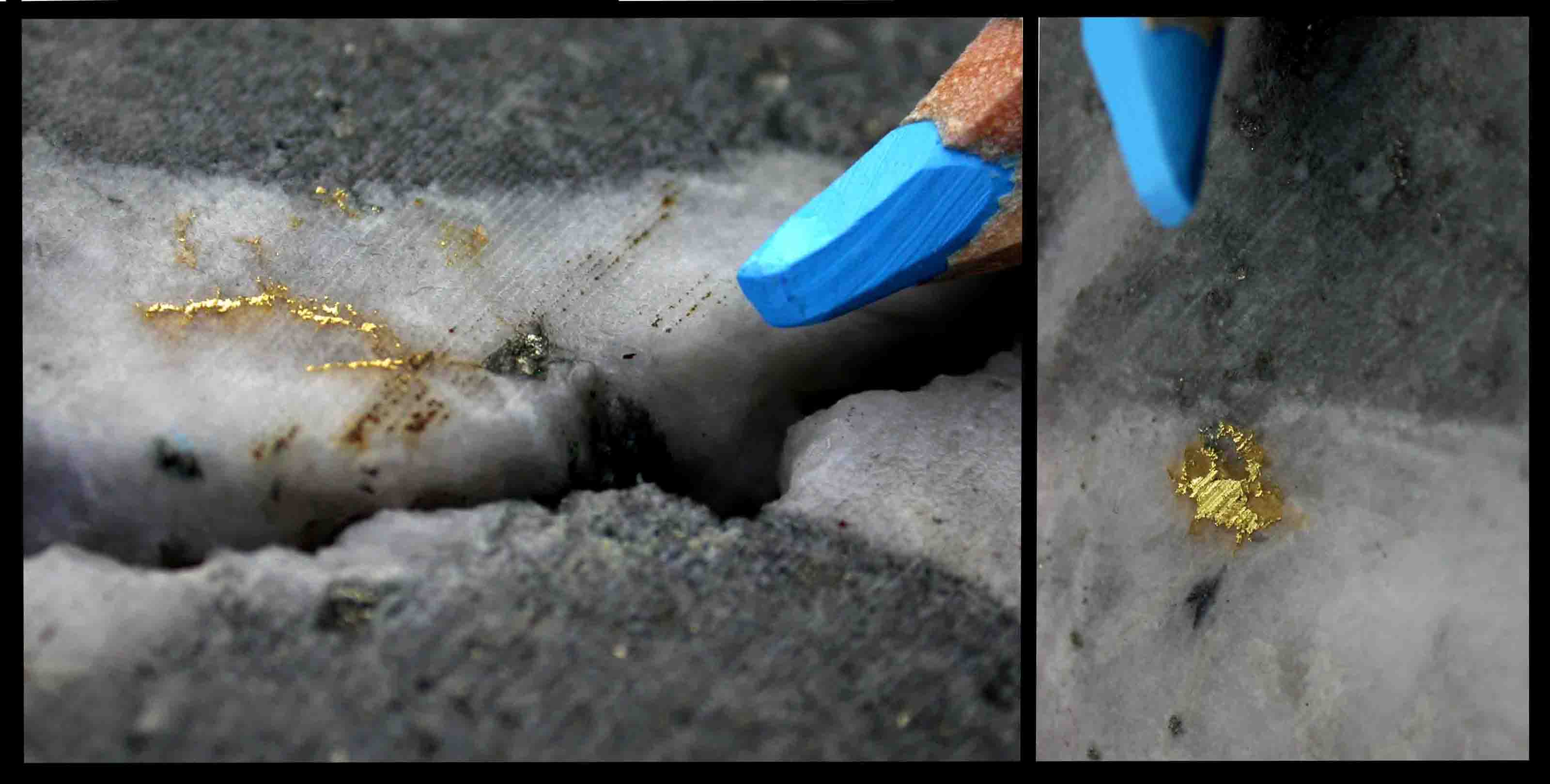
Photo Above: The diamond blade used to cut core is approximately the width of these gold grains. The saw blade will destroy the grains leaving little gold for either surviving half of the core or double the grade of half of the core and leave zero gold in the other half of the core.
X-Ray Analysis Core Testing and the Surface Enrichment Effect
Malleable minerals including Gold, Silver and Argentite (AgS) are pushed to the side of the drill bits and as a smear on the core surface. The smear increases the apparent surface area of the mineral, increasing the apparent visual estimate of valuable metal.
The price of Z-Ray analysis machines has dropped making it an affordable tool for routine logging of core. This machine penetrates a short distance into the core measuring the gold or silver content of the skin of the core. It is safe to assume the outer surface has a disproportionate impact relative to the core near the penetration limit.
It is safe to assume X-Ray analysis machines will have two artificial apparent enrichment effects when measuring malleable precious metals in drill core.
- The actual real metal content of the detection skin will be artificially increase by the addition of smeared metal.
- The X-Ray analyzer analysis will be decrease with skin depth with the greatest contribution from the thin metal smear on the surface of the core.
It would be easy to test this effect by analyzing five core surfaces, then polishing off the surface smear with very fine emery cloth, the reanalyzing the core without the smear. The (smeared analysis)/(polished analysis) would be a reasonable measure of the smear effect. A ratio of 1.00 would prove the smear effect is not real and X-Ray analysis of raw core is real to the limits of the machine’s ability.
When core is polished removing the smeared malleable metal, the apparent intersection area of malleable metal decreases and the true outline of the mineral texture becomes sharp showing the actual edges of the metal. The mineral relationship will be clearly defined.
Photo Above: Gold smeared by diamond drill bit. If the core were polished with very fine emery paper the surface area of the gold would decrease exposing the true edges of the gold.
Photo Above: Silver vein. If the core were polished with very fine emery paper the surface area of the gold would decrease clearly expose the actual mineral outlines .
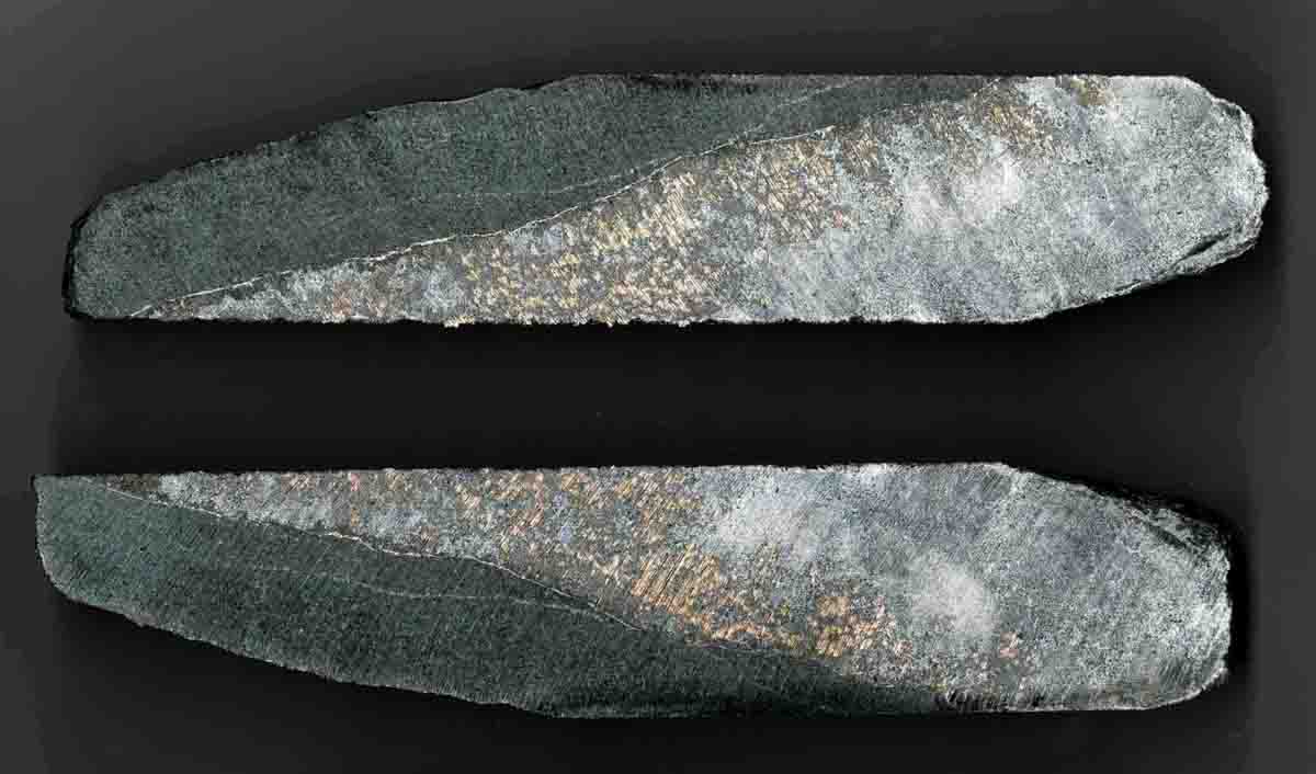
Photo Above: The sawn core has a smear effect similar to a diamond drill bit. The true textural relationship of the silver and the cobalt mineralization is somewhat masked by smeared silver
Logging Lost Core
Sometimes during drilling part of the rock is not recovered as core. This is commonly called lost core or ground core. Logging lost core can be an important part of certifying logging within important core, particularly if it is in an ore intersection or an ore block.
An informed decisions regarding lost core logging are made as the core is logged. Often there is an explanation for the missing core.
Sometimes the core spring that grasps the core and holds that core in the core tube malfunctions and some core falls back into the hole. That core is often over-ground resulting in lost core. Sometimes over-ground core is recovered as moon and curved shaped core pieces. The driller commonly reports this problem in the daily work report and as a note inscribed on a marker in the core box. Overground core can be distinguished from caved rock from up the hole from broken or faulted ground (caved is commonly rock worn rounded rock. This rock can commonly be identified as a rock type encountered in broken or faulted ground up the hole. Cave is excluded from the core measurement because it did not originate from the cored ground. It is logged comment independent of the recovered core.
Commonly two pieces of adjoining core will both have smooth butt ends worn flat by spinning in the core tube.
Sometimes the ground is so incompetent that is cannot be recovered.
In a few situation the drill hole crosses a void with no rock. Sometime drill holes encounter mine workings. Natural open hole and mine workings are not lost core and can be treated as a rock type for logging purposes. An open hole or void can be treated as a legitimate rock type because open space is a description of what the drill encountered.
I have had the driller report drilling into mine workings and the driller often reports the width of the working and frequently continued drilling past the mine opening. Other times the driller cannot cross and re-collar the hole on the other side. T the Kerr mine in Cobalt a driller recovered rack spike. In a hole at the Castle mine, the driller recovered mine timber in a void and continued drilling over a hundred or so meters past the void. The driller pulled the rods and changed the drill bit. In reentering the hole he core through the mine timber again. The timber marked the beginning of the next run in the core box.